Views:
Steam boiler systems are used in a wide variety of industrial applications for generating heat or for providing hot water. A steam boiler system diagram provides a visual representation of the components and connections in the system. It is a useful tool for understanding how the system operates and for troubleshooting any issues that may arise. In this article, we will provide an overview of steam boiler system diagrams and discuss the various components and connections that they contain.
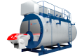
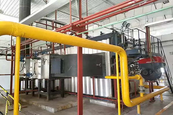
A steam boiler system diagram typically consists of several components and connections. The most basic components are the boiler, the return system, the feedwater system, and the condensate return system. The boiler is the main component in the system and is responsible for heating the water to create steam. The return system is used to return the steam to the boiler after it has been used. The feedwater system is used to supply the boiler with water, and the condensate return system is used to return any condensate from the system back to the boiler.
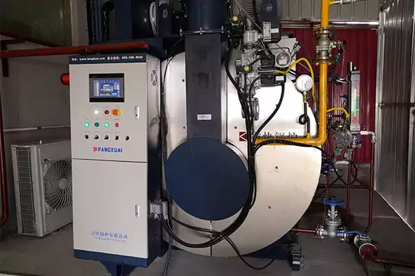
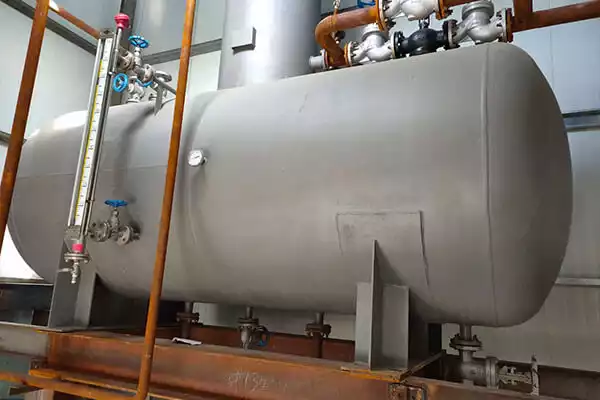
The other components in a steam boiler system diagram are the steam-water separator, the steam trap, the control valves, the pressure gauge, the safety valve, and the pressure relief valve. The steam-water separator is used to separate the steam from the water in the system. The steam trap is used to trap any steam that escapes from the system. The control valves regulate the flow of steam and water in the system. The pressure gauge is used to measure the pressure in the system, and the safety valve is used to prevent the system from over-pressurizing. The pressure relief valve is used to release steam and pressure if the system becomes too pressurized.
In addition to the components listed above, a steam boiler system diagram may also include additional components such as the expansion tank, the blowdown valve, the fuel supply system, and the combustion air supply system. The expansion tank is used to store excess water in the system. The blowdown valve is used to reduce the amount of solids in the system. The fuel supply system is used to supply fuel to the boiler, and the combustion air supply system is used to provide air for the combustion process.
Steam boiler system diagrams are an essential tool for anyone working with steam boiler systems. They provide a visual representation of the components and connections in the system, allowing for a better understanding of how the system works and how to troubleshoot any issues that may arise. Understanding the components and connections in a steam boiler system diagram is essential for ensuring that the system is functioning properly and safely.
Gas boiler engineer training is essential for anyone looking to work as a boiler engineer. Boilers are a vital part of any home or commercial building, providing heat and hot water to the occupants. As such, it is important that any boiler engineer is properly trained and qualified to carry out t
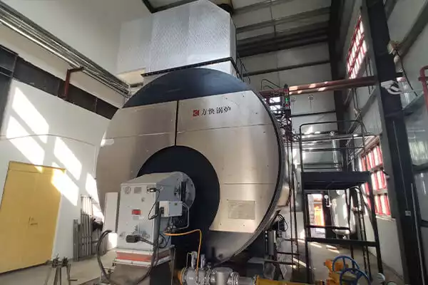
2021.11.03>Combi boiler heaters are an essential part of any home's heating system. They provide hot water on demand, making them a convenient and efficient way to heat your home. In this guide, we'll discuss the basics of combi boiler heaters, the benefits of using them, and how to choose the right one for
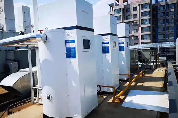
2021.11.03>Wall mounted boilers are a popular choice for homeowners and businesses alike, thanks to their space-saving design, energy efficiency, and convenience. But with so many models on the market, it can be difficult to find the right one for your needs. This guide will help you understand the features
2021.11.03>80% fo the industry leaders, choost FANGKUAI
Contact us for more details about our
boilers, solutions and services !
Copyright © Zhengzhou Fangkuai Boiler Co., Ltd