Views:
Gas boiler parts diagrams provide an important reference for homeowners and technicians who need to understand the components of a gas boiler system. Gas boilers are a common source of heat in many homes, and understanding their parts and how they work is essential for maintaining their efficiency and safety. In this article, we will examine the most common gas boiler parts diagrams, and discuss the purpose of each component and its function in the system.
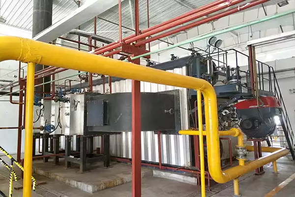
The first part of a gas boiler parts diagram is the combustion chamber. This is where the fuel is burned, and the heat produced is used to heat water in the boiler. The combustion chamber is typically made of metal, and is surrounded by an insulation material to keep the heat in and reduce the risk of fire. Inside the combustion chamber, the fuel is burned with the help of an air-fuel mixture, which is regulated by the thermostat.
The next part of a gas boiler parts diagram is the heat exchanger. The heat exchanger is responsible for transferring the heat from the combustion chamber to the water in the boiler. It is typically made of copper or stainless steel, and is usually connected to the combustion chamber by a flue pipe. The heat exchanger is also equipped with a safety valve, which is designed to prevent the water from overheating and causing a fire.
The third part of a gas boiler parts diagram is the flue pipe. This is the pipe that connects the combustion chamber to the heat exchanger. The flue pipe is typically made of metal, and is designed to allow the hot air and gases produced by the combustion process to escape safely. The flue pipe is also equipped with a safety valve, which is designed to prevent the flue gases from escaping into the home.
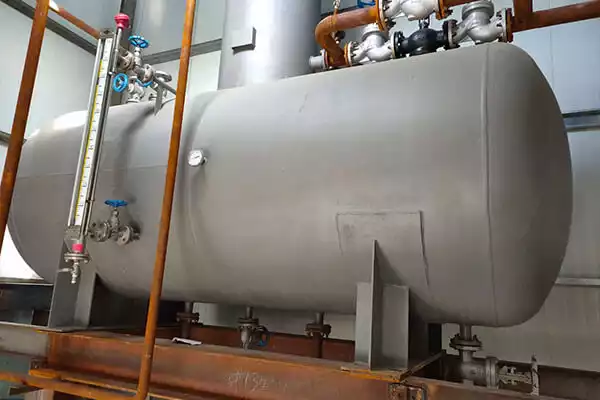
The fourth part of a gas boiler parts diagram is the expansion tank. This is a container that is used to store excess water in the system. The expansion tank is typically made of metal, and is connected to the heat exchanger by a pressure relief valve. The expansion tank is designed to prevent the water from becoming too hot and causing a fire.
The fifth part of a gas boiler parts diagram is the water pump. This is the device that circulates the water through the system to ensure that the heat is evenly distributed. The water pump is typically made of metal, and is connected to the heat exchanger by a pressure relief valve. The water pump is also equipped with a safety valve, which is designed to prevent the water from becoming too hot and causing a fire.
These are the five most common parts of a gas boiler parts diagram. Understanding the purpose of each component and its function in the system is essential for maintaining the efficiency and safety of a gas boiler system. If you need help understanding a gas boiler parts diagram, contact a professional technician who can provide you with the information you need.
Gas boiler engineer training is essential for anyone looking to work as a boiler engineer. Boilers are a vital part of any home or commercial building, providing heat and hot water to the occupants. As such, it is important that any boiler engineer is properly trained and qualified to carry out t
2021.11.03>Combi boiler heaters are an essential part of any home's heating system. They provide hot water on demand, making them a convenient and efficient way to heat your home. In this guide, we'll discuss the basics of combi boiler heaters, the benefits of using them, and how to choose the right one for
2021.11.03>Wall mounted boilers are a popular choice for homeowners and businesses alike, thanks to their space-saving design, energy efficiency, and convenience. But with so many models on the market, it can be difficult to find the right one for your needs. This guide will help you understand the features
2021.11.03>80% fo the industry leaders, choost FANGKUAI
Contact us for more details about our
boilers, solutions and services !
Copyright © Zhengzhou Fangkuai Boiler Co., Ltd